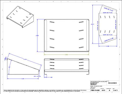
How To Note Flatness Sheet Metal Drawings
Gd T Tips Free State

Quiz Question 8 Geo Tolerances Answers Technical Drawing Engineering Design Geometric Tolerancing

Quiz Question 8 Geo Tolerances Answers Technical Drawing Engineering Design Geometric Tolerancing

Wallet Sized Gd T Symbol Reference Card Omnia Mfg Engineering Symbols Geometric Tolerancing Mechanical Engineering Design

Eliminate Your Fears And Doubts About Mechanical Engineering Drawing Symbols Engineering Symbols Mechanical Engineering Design Mechanical Design

Engineering Drawings Gd T For The Quality Engineer Mechanical Engineering Design Mechanical Engineering Engineering Symbols

Yes new in 2009 drawing callout.
How to note flatness sheet metal drawings.

Gd T Symbols Mechanical Engineering Design Mechanical Design Engineering Symbols

Geometric Tolerances Investment Castings To Precise Geometric Tolerances Milwaukee Precision Geometric Tolerancing Geometric Mechanical Engineering Design
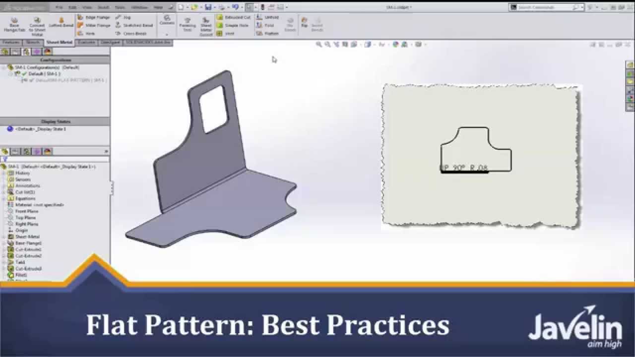
Solidworks Sheet Metal Tutorial Flat Pattern Best Practices Youtube
Flatness Gd T Basics

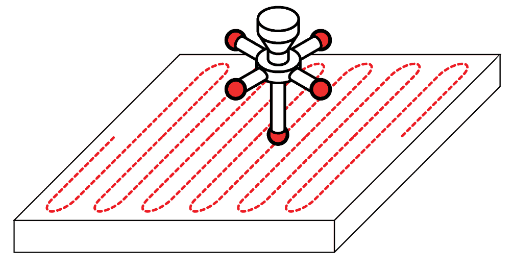
Following Dfm Guidelines For Working With Sheet Metal Machine Design

Storyboard Background Tips From Spongebob Artist Sherm Cohen In 2020 Comic Tutorial Spongebob Drawings Comic Drawing

Coining And Embossing Around Flared Holes Improves A Part S Strength And Its Ability To Maintain Its Fla Sheet Metal Mechanical Engineering Design Metal Design
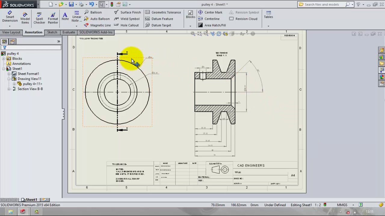
Drafting And Add Gd T In Solidworks Tutorial Youtube

Csvm Construction Log 5 Block Shaping Blocks Violin

Pin On Technical Drawing
Https Docs Plm Automation Siemens Com Data Services Resources Se 109 Se Help En Us Selfpacedext Pdf Mt01419 Pdf
Https Www Qualitymag Com Ext Resources Files Gdt Gdt Resource Updated Pdf

Casing Windows Jlc Online Molding Millwork And Trim Carpentry Windows Building Windows Molding And Millwork Window Installation

Gutter Maintenance Everything Gutter Box Gutter Parapet Butterfly Roof
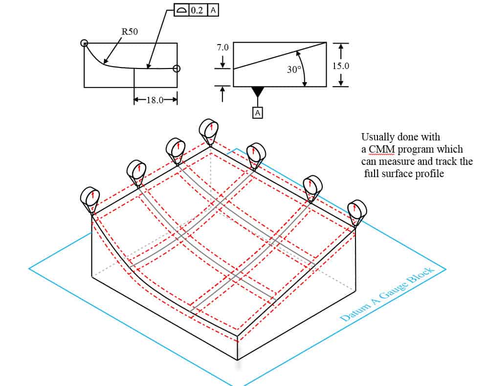
Profile Of A Surface Gd T Basics

Parallelism Gd T Basics

Dallas Galvalume 24 Gauge Metal Roofing Systems Metal Roof Metal Roofing Systems Zinc Roof
Catia Gd T Tutorial 9 Youtube
Https Encrypted Tbn0 Gstatic Com Images Q Tbn 3aand9gcq53f8tkskz2ngohfg4jijc6vbdqj86 M0 Ftxbbalurm2eh8v5 Usqp Cau

Csvm Construction Log 5 Block Shaping Violin Design Chicago School Blocks
Wall Covering Steel Panels Stainless Steel Panels Interior Cladding Wall Cladding Designs

New Manufacturing Blueprint Symbols Diagram Wiringdiagram Diagramming Diagramm Visuals Visualisation G Blueprint Symbols Geometric Tolerancing Geometric

New To Creo 4 0 Creating Editing Geometric Tolerances Gtols Youtube
3 D Cad Productivity Reliability And Responsiveness
Source : pinterest.com
